 Hot new
 Hot new
 Hot new
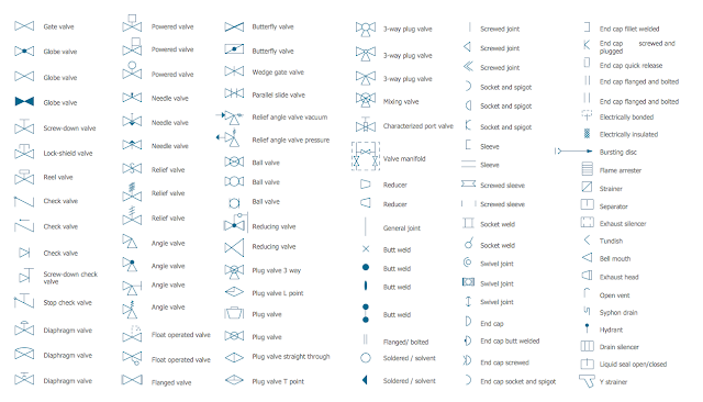
How to read a piping and instrumentation drawing?
A piping and instrumentation diagram (P&ID) is a detailed diagram in the process industry which shows the piping and vessels in the process flow, together with the instrumentation and control devices. They usually contain the following information:
Process piping, sizes and identification, including:
Pipe classes or piping line numbers, Flow directions, Interconnections references
Permanent start-up, flush and bypass lines
Mechanical equipment and process control instrumentation and designation (names, numbers, unique tag identifiers), including:
Valves and their identifications (e.g. isolation, shutoff, relief and safety valves)
Control inputs and outputs (sensors and final elements, interlocks)
Miscellaneous - vents, drains, flanges, special fittings, sampling lines, reducers and increasers
Interfaces for class changes
Computer control system
Identification of components and subsystems delivered by others
To learn more on the "Basic guidelines and applications of Control Valves"P&IDs are originally drawn up at the design stage from a combination of process flow sheet data, the mechanical process equipment design, and the instrumentation engineering design. During the design stage, the diagram also provides the basis for the development of system control schemes, allowing for further safety and operational investigations, such as a Hazard and operability study (HAZOP). To do this, it is critical to demonstrate the physical sequence of equipment and systems, as well as how these systems connect.