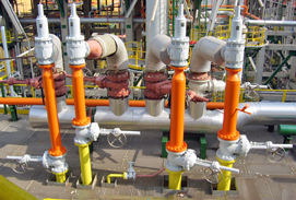
The function of a pressure relief valve is to protect pressure vessels,
piping systems, and other equipment from pressures exceeding their
design pressure by more than a fixed predetermined amount.The aim of
safety systems in processing plants is to prevent damage to equipment,
avoid injury to personnel and to eliminate any risks of compromising the
welfare of the community at large and the environment. Proper sizing,
selection, manufacture, assembly, test, installation, and maintenance of
a pressure relief valve are critical to obtaining maximum protection.
The pressure relief valve must open at a predetermined set pressure,
flow at rated capacity at a specified overpressure, and close when the
system pressure has returned to a safe level. Pressure relief valves
must be designed with materials compatible with many process fluids from
simple air and water to the most corrosive media. These design
parameters lead to the wide array of pressure relief valve products
available in the market today.
Types of Pressure Relief Valves:
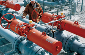
The standard design safety relief valve is spring loaded with an
adjusting ring for obtaining the proper blowdown and is available with
many optional accessories and design features. The bellows and balanced
bellows design isolate the process fluid from the bonnet, the spring,
the stem, and the stem bushing with a bellows element. Jacketed valve
bodies are available for applications requiring steam or heat transfer
mediums to maintain viscosity or prevent freezing. Pilot-operated valves
are available with the set pressure and blowdown control located
in a separate control pilot. This type of valve uses the line pressure
through the control pilot to the piston in the main relief valve and
thereby maintains a high degree of tightness, especially as the set
pressure is being approached. Another feature of the pilot-operated
valve is that it will permit a blowdown as low as 2 %. The disadvantage
of this type of valve is its vulnerability to contamination from foreign matter in the fluid stream
Sizing of Pressure Relief Valves:
Correct and comprehensive pressure
relief valve sizing is a complex multi-step process that should follow the
following stepwise approach:
1. Each piece of equipment in a
process should be evaluated for potential overpressure scenarios.
2. An appropriate design basis must
be established for each vessel. Choosing a design basis requires
assessing alternative scenarios to
find the credible worst case scenario.
3. The design basis is then used to
calculate the required pressure relief valve size. If possible, the sizing
calculations should use the most
current methodologies incorporating such considerations as two
phase flow and reaction heat sources.
In order to properly select and size a pressure relief valve, the
following information should be ascertained for each vessel or group of
vessels which may be isolated by control or other valves. The data
required to perform pressure relief valve sizing calculations is quite
extensive, Let me briefly explain the sam. First, the equipment
dimensions and physical properties must be assembled. Modeling heat flow
across the equipment surface requires knowledge of the vessel
material’s heat capacity, thermal conductivity, and density (if vessel
mass is determined indirectly from vessel dimensions and wall
thickness). The vessel geometry – vertical or horizontal cylinder,
spherical, etc. – is a necessary parameter for calculating the wetted
surface area, where the vessel contents contact vessel walls. Second,
the properties of the vessel contents must be quantified.This includes
density, heat capacity, viscosity, and thermal conductivity. Values of
each parameter are required for both liquid and vapor phases. Boiling
points, vapor pressure, and thermal expansion coefficient values also
are required. Ideally, the properties will be expressed as functions of
temperature, pressure, and compositions of the fluid.
The most difficult aspect of the
design and sizing of pressure relief valves is ascertaining the controlling
cause of overpressure. This is
sometimes referred to as the worst case scenario. Overpressure in
equipment may result from a number
of causes or combination of causes. Each cause must be
investigated for its magnitude and
for the probability of its occurrence with other events. The objective
might be to document why the
particular design basis is the correct choice.

 Hot new
 Hot new
 Hot new